Mit dieser Library kann der DAC vom STM32F4 (entweder einer oder beide) per DMA betrieben werden.
Der Sinn ist, eine Kurvenform per DAC (zyklisch) auszugeben. Dazu müssen die Datenwerte der Kurve in einem Array vorliegen.
Ich hab in der Library mal zum Test 4 Kurvenformen eingetragen
(Sinus, Sägezahn, Dreieck, Rechteck … und noch eine für ein Dauer-Lo-Pegel)
Mit einer extra Funktion kann die Frequenz der Kurvenform eingestellt werden. Wobei man eigentlich den Vorteiler und den Comparewert vom Timer einstellt. Diese beiden Werte muss man vorher ausrechnen.
(die Frequenz ist auch Abhängig wie viele Datenwerte die Kurvenform besitzt)
Welcher Timer benutzt werden soll, muss im H-File per Define eingestellt werden.
Ich hab Timer6 und Timer7 benutzt, es geht aber auch TIM2, TIM4,TIM5)
Beim DAC per DMA scheint ein BUG vorzuliegen, wenn die Variable “DAC_InitStructure” nicht Global definiert wird, kommt es sporadisch zu Fehlern das der DAC nicht läuft.
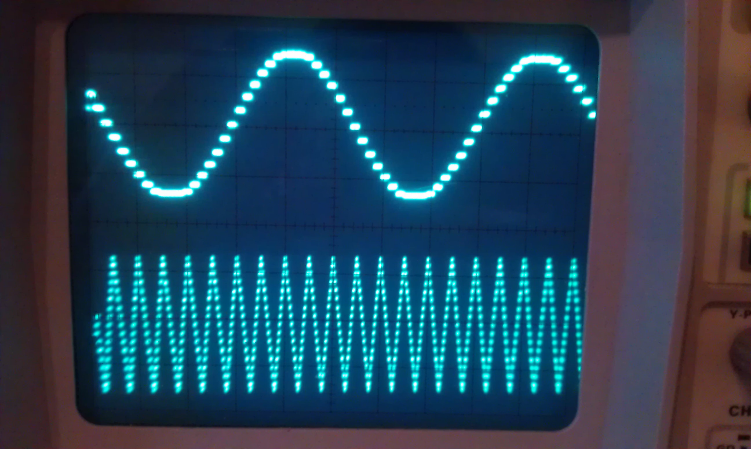
Beispielbild :
Die DA-Wandler liegen an festen Pins der CPU :
1 2 | DAC1 an PA4 DAC2 an PA5 |
Voraussetzungen :
1 2 | Benutzte Module der CooCox-IDE : GPIO, DAC, DMA, TIM Benutzte Librarys : keine |
Enumerationen :
1 2 3 4 5 | typedef enum { SINGLE_DAC1_DMA = 0, // nur DAC1 an PA4 benutzen SINGLE_DAC2_DMA, // nur DAC2 an PA5 benutzen DUAL_DAC_DMA // DAC1 (PA4) und DAC2 (PA5) benutzen }DAC_DMA_MODE_t; |
.
1 2 3 4 5 6 7 | typedef enum { DAC_WAVE_OFF = 0, // Dauer Lo-Pegel DAC_WAVE1_SINUS = 1, // Waveform1 (Sinus) DAC_WAVE2_SAEGEZAHN = 2, // Waveform2 (Sägezahn) DAC_WAVE3_DREIECK = 3, // Waveform3 (Dreieck) DAC_WAVE4_RECHTECK = 4 // Waveform4 (Rechteck) }DAC_DMA_WAVE_NAME_t; |
Funktionen :
1 2 3 4 5 | void UB_DAC_DMA_Init(DAC_DMA_MODE_t mode); // um den DAC zu initialisieren void UB_DAC_DMA_SetWaveform1(DAC_DMA_WAVE_NAME_t wave); // zum einstellen einer Kurvenform für DAC1 void UB_DAC_DMA_SetWaveform2(DAC_DMA_WAVE_NAME_t wave); // zum einstellen einer Kurvenform für DAC2 void UB_DAC_DMA_SetFrq1(uint16_t vorteiler, uint16_t periode); // zum einstellen der Frq von DAC1 void UB_DAC_DMA_SetFrq2(uint16_t vorteiler, uint16_t periode); // zum einstellen der Frq von DAC2 |
Beispiel :
1 2 3 4 5 6 7 8 9 10 11 12 13 14 15 16 17 18 19 20 21 22 23 24 25 26 27 28 29 30 31 32 33 34 35 36 37 38 39 40 41 42 43 44 45 46 47 | //-------------------------------------------------------------- // File : main.c // Datum : 24.03.2013 // Version : 1.0 // Autor : UB // EMail : mc-4u(@)t-online.de // Web : www.mikrocontroller-4u.de // CPU : STM32F4 // IDE : CooCox CoIDE 1.7.0 // Module : CMSIS_BOOT, M4_CMSIS_CORE // Funktion : Demo der DAC-DMA Library // Hinweis : Diese zwei Files muessen auf 8MHz stehen // "cmsis_boot/stm32f4xx.h" // "cmsis_boot/system_stm32f4xx.c" //-------------------------------------------------------------- #include "main.h" #include "stm32_ub_dac_dma.h" int main(void) { SystemInit(); // Quarz Einstellungen aktivieren // init vom DAC im DMA-Mode (DAC-1 und DAC-2) UB_DAC_DMA_Init(DUAL_DAC_DMA); // an DAC1 (PA4) ein Sinus-Signal ausgeben UB_DAC_DMA_SetWaveform1(DAC_WAVE1_SINUS); // an DAC2 (PA5) ein Dreieck-Signal ausgeben UB_DAC_DMA_SetWaveform2(DAC_WAVE3_DREIECK); // Frq vom Sinus-Signal auf 1 Hz stellen // Das Sinus-Signal ist 32 Werte lang // f=84MHz/300/8750/32 = 1 Hz UB_DAC_DMA_SetFrq1(299,8749); // Frq vom Dreieck-Signal auf 10 Hz stellen // Das Dreieck-Signal ist 32 Werte lang // f=84MHz/30/8750/32 = 10 Hz UB_DAC_DMA_SetFrq2(29,8749); while(1) { } } |
Hier die Library zum Download :
Hier der komplette CooCox-Projektordner zum Download :
9 Antworten auf 24-DAC_DMA-Library (STM32F4)
Wie hat Dir dieser Artikel gefallen?
 (Noch keine Bewertungen)
wie viel Kanäle gehen gleichzeitig beim F4 ?
Der STM32F4 hat intern zwei DAC Kanäle.
Hello,
this program is awesome. I need to do something similar with the same board (STM32F4). I need to make a rectangular wave and transmit that to a h-bridge (chip) and then to an ultrasonic sensor. The thing is that the chip works between 4,5 and 36 V. The other thing is that the chip works with digital signal so it’s not necessary to convert from digital to analog.
Can someone help me please?
In an other blog someone told me that I need to connect a extern pull-up resistor or something like this.
Thank you
I think you can try level shifter, like this:
https://www.sparkfun.com/products/12009
And an article I found useful:
http://codeandlife.com/2012/04/06/level-shifting-101/
It’s very cool project.
If I need DAC1 and DAC2 output sample wave, for example sine waves, I want to set amplitude/frequence, as well as the phase-shift between DAC1 and DAC1 . How can I do this?
thank you
you can copy the sinus array into ram and shift the phase by reordering the items. But the original sinus array has only 32 items, so the smallest shift is about 11 degree. If you want a better result, increase the number of items.
Can the output voltage only be 0~3V? or can be -1.5~+1.5V as well as -3~0V.
you need an external level shifter . search in google how to do that with an op and some resistors.