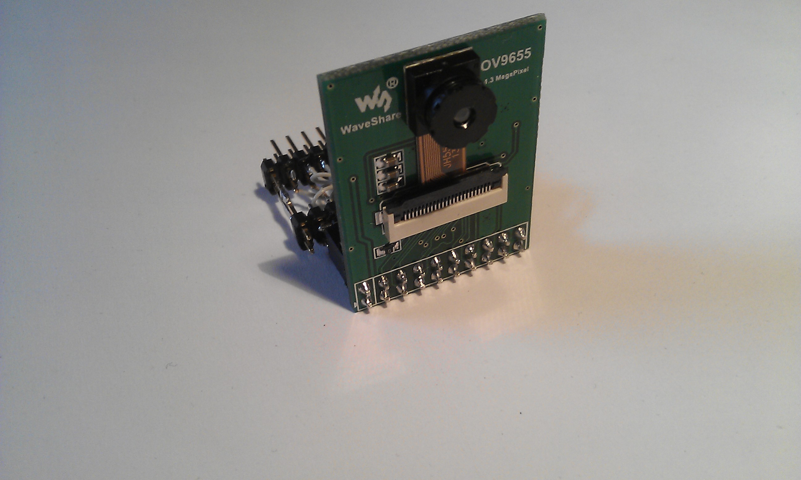
Mit dieser Library kann ein 1,3MPixel Digital-Camera-Modul (mit OV9655-Chip) per DMA und DCMI-Interface an das STM32F4 Discovery-Board angeschlossen werden.
Das Modul gibts für ca. 15 EUR z.B. bei EBay. Und hat eine max Auflösung von 1280×1024 Pixel (SXGA) und eine Farbtiefe von 16bit.
Die Kommunikation mit dem Chip läuft über I2C (max 400kHz) und die Bilddaten werden per 8bit DCMI-Bus übertragen. Mit einer Framerate von 15 Bilder/sec (bei SXGA) und 30 Bilder/sec (bei QVGA).
Da ich die Bilder auf meine LC-Display anzeigen will, habe ich im Moment nur die QVGA Auflösung (320×240 Pixel) und QQVGA (160×120 Pixel) in der Library implementiert.
Der Datentransfer von der Camera zum Display geschieht über einen DMA-Kanal, somit muss die CPU dabei gar nichts machen. Und das Bild wird flüssig dargestellt.
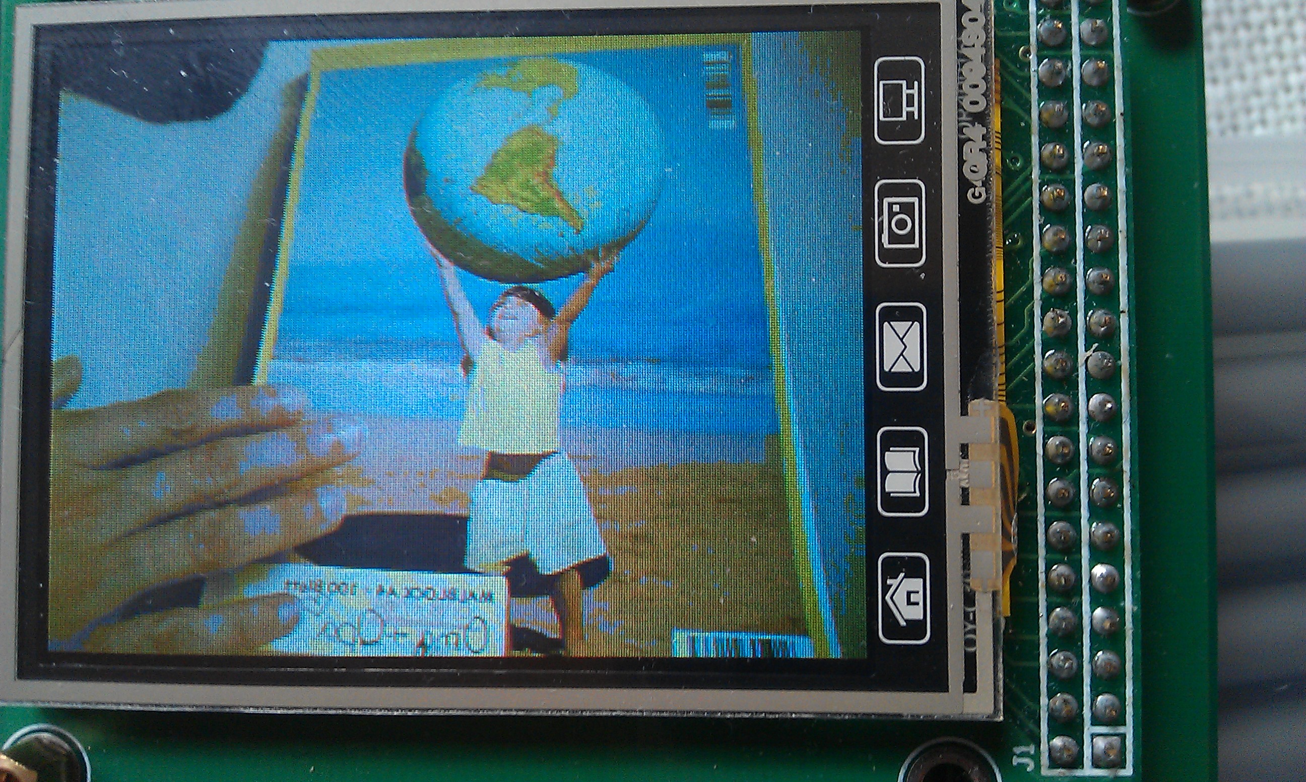
(Im Moment ist das Bild noch spiegelverkehrt…das liegt am Landscape-Mode, mal sehen ob ich das noch fixen kann)
Die Version 1.1 kann jetzt auch einzelbilder “Snapshots” machen.
Und wenn die Auflösung 160 x 120 Pixel gewählt ist, kann auch ein Snapshot
ins RAM gemacht werden. Die Bild-Daten landen dann nicht auf dem Display
sondern in einem RAM-Array und können von dort mit der Funktion
“UB_OV9655_RAM2BMP” in ein BMP-Bildformat gewandelt werden.
Die Funktion sendet die Daten auch gleich per UART zu einem PC
(dafür wird die UART Library benötigt)
Hinweis : ein paar DCMI-Pins der CPU werden auf dem Discovery-Modul schon vom Sound-DAC (CS43L22) und dem Beschleunigungs-Sensor (LIS302) belegt.
(PA4, PA6, PB6, PB9, PC7) Ich konnte hier bei mir keine Probleme feststellen allerdings werden die beiden ICs wohl dann nicht gleichzeitig nutzbar sein.
Wichtiger Hinweis zum Trägerboard :
Wer das gleiche Trägerboard wie ich benutzt,
muss zwei Leiterbahnen darauf auftrennen und umverdrahten:
Die standard Belegung der DCMI-Buchse (CON6) sieht vor für D2 und D3 die CPU-Pins PE0 und PE1 zu benutzen. Da liegen aber die Interrupt Ausgänge vom LIS302 drauf und der zieht die Leitungen immer auf Lo-Pegel !! Ich hab die beiden Leiterbahnen auf der Unterseite vom Trägerboard aufgetrennt (CON6 Pin 1 und 3) und 2 Drähte zu den CPU-Pins PC8 und PC9 gelegt (diese werden auf dem Discovery-Modul noch nicht benutzt…und da liegen auch D2 und D3 vom DCMI drauf)
Und noch was -> die 18pol Buchse CON6 ist zwar im Schaltplan mit OV9655 beschriftet, das Modul ist aber NICHT Pinkompatibel -> es muss also ein Adapter gelötet werden !!
Das Modul braucht einen Eingangs-Clock (10 MHz bis 48 MHz) ich hab zuerst einen GPIO-Pin dazu benutzt aber jetzt hab ich einen 16MHz Quarzoszillator drangelötet. Der Standardwert sind eigentlich 24MHz aber den hatte ich nicht hier ![]()
Weil die I2C-Schnittstelle und das Display benutzt wird, sind die zwei Librarys “STM32_UB_LCD_ST7783″ und “STM32_UB_I2C1″ notwendig.
Um das QQVGA-Bild auf dem Display in einem Window darstellen zu können, habe ich die Display-Library angepasst. (Version 1.5)
Beispielbilder :
- hier das OV9655-Modul
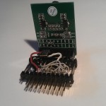
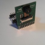
- und von hinten

- Hier eine Bild vom Display
Benutzte Pins und DMAs :
1 2 3 4 5 6 7 8 9 10 11 12 13 14 15 16 17 18 19 20 21 22 23 24 | PA4 -> DCMI_HSYNC = Camera HSYNC (HREF) PA6 -> DCMI_PCLK = Camera PIXCLK (PCLK) PB6 -> DCMI_D5 = Camera D5 (D7) PB7 -> DCMI_VSYNC = Camera VSYNC (VSYNC) PB8 -> I2C1-SCL = Camera I2C-SCL (SIOC) PB9 -> I2C1-SDA = Camera I2C-SDA (SIOD) PC6 -> DCMI_D0 = Camera D0 (D2) PC7 -> DCMI_D1 = Camera D1 (D3) PC8 -> DCMI_D2 = Camera D2 (D4) PC9 -> DCMI_D3 = Camera D3 (D5) PE4 -> DCMI_D4 = Camera D4 (D6) PE5 -> DCMI_D6 = Camera D6 (D8) PE6 -> DCMI_D7 = Camera D7 (D9) (*) Texte in Klammer beschreiben den Aufdruck auf dem OV9655-Modul DMA : entweder DMA2_STREAM1_CHANNEL1 oder DMA2_STREAM7_CHANNEL1 Camera (GND) = GND Camera (Vcc) = 3,3V Camera (XCLK) = 24MHz (10...48MHz) Camera (PWDN) = nc Camera (RET) = nc |
Voraussetzungen :
1 2 | Benutzte Module der CooCox-IDE : DCMI, DMA Benutzte Librarys : STM32_UB_I2C1, STM32_UB_LCD_ST7783 |
Enumerationen :
1 2 3 4 5 6 7 8 | typedef enum { OV9655_OK =0, // OV9655 OK OV9655_I2C_ERR, // Fehler bei I2C OV9655_MIDH_ERR, // Fehler bei ID-HIByte OV9655_MIDL_ERR, // Fehler bei ID-LoByte OV9655_PID_ERR, // Fehler bei Produkt-ID OV9655_LCD_ERR // Fehler beim Display }OV9655_ERR_t; |
Funktionen :
1 2 3 4 5 6 7 | OV9655_ERR_t UB_OV9655_Init(void); // Init vom OV9655 void UB_OV9655_CaptureStart(void); // start vom Capture-Mode void UB_OV9655_CaptureStop(void); // stop vom Capture-Mode void UB_OV9655_Snapshot(void); // macht eine einzelne Aufnahme void UB_OV9655_SetHelligkeit(uint8_t wert); // einstellen der Helligkeit void UB_OV9655_Snapshot2RAM(void); // macht einen Snapshots ins RAM void UB_OV9655_RAM2BMP(void); // erstellt ein BMP-File |
Beispiel :
1 2 3 4 5 6 7 8 9 10 11 12 13 14 15 16 17 18 19 20 21 22 23 24 25 26 27 28 29 30 31 32 33 34 35 36 37 38 39 40 41 42 | //-------------------------------------------------------------- // File : main.c // Datum : 29.03.2013 // Version : 1.0 // Autor : UB // EMail : mc-4u(@)t-online.de // Web : www.mikrocontroller-4u.de // CPU : STM32F4 // IDE : CooCox CoIDE 1.7.0 // Module : CMSIS_BOOT, M4_CMSIS_CORE // Funktion : Demo der OV9655-Library (Camera per DCMI) // Hinweis : Diese zwei Files muessen auf 8MHz stehen // "cmsis_boot/stm32f4xx.h" // "cmsis_boot/system_stm32f4xx.c" //-------------------------------------------------------------- #include "main.h" #include "stm32_ub_ov9655.h" int main(void) { OV9655_ERR_t check; SystemInit(); // Quarz Einstellungen aktivieren // init vom Camera-Modul (OV9655) check=UB_OV9655_Init(); if(check==OV9655_OK) { // wenn alles OK -> Capture-Mode starten UB_OV9655_CaptureStart(); } else { // bei einem Fehler // roten Bildschirm anzeigen UB_LCD_FillScreen(RGB_COL_RED); } while(1) { } } |
Hier die Library zum Download :
Hier der komplette CooCox-Projektordner zum Download :
18 Antworten auf 27-DCMI_OV9655-Library (STM32F4)
Wie hat Dir dieser Artikel gefallen?
 (Noch keine Bewertungen)
Hi,
eine weitere tolle library …
Würde sie gerne benutzen, jedoch ohne ein basis board, sondern selbst gefädelt.
Problem ist dass mein camera board von wafeshare eine andere Beschriftung aufweist.
Ich nehme an SIOC ist SCL und SIOD ist SDA. Die Daten Pins zählen D2…D9
Ist dann Camera D0 in deiner Beschreibum D2 bei mir?
PWDN, XCLK und RET gibt es auch noch die bei Dir nicht definiert sind?
Hab auch ein anderes display das per SPI angesteuert wird. Muss dann wahrscheinlich die daten ins RAM schreiben lassen und von dort per SPI verschicken – oder?
Würde mich sehr über hinweise freuen.
Danke.
Hi, du hast recht :
SIOC=SCL, SIOD=SDA, D2=D0 … D9=D7
PWD und RET können offen bleiben aber an XCLK muss ein 24MHz Quarz angeschlossen werden (du kannst auch MC0 der CPU dafür programmieren)
Für ein Display mit SPI-BUS hab ich schon eine Library, kannst dich ja an der orientieren (67=ILI9341-SPI) einen Buffer im RAM brauchst du nicht, das Display hat ja sicher einen Bildspeicher. Es reicht die Pixel die angezeigt/geändert werden sollen, per SPI zum LCD zu senden.
Hi
I’m using STM32F4 DCMI with the OV9655 Camera. I set the camera to RGB565 format. My camera is working, but the color is not right.
This is the test Video https://www.youtube.com/watch?v=yTBqYgAgdZQ
What is the cause of the problem?
Regards
Is the setting from the LCD also in RGB565 ? And have you tested the display standalone if all colors are ok …Full RED, Full Green, Full Blue ? This is a odd failure because the DCMI is a bus and actually no color cant be lost. Event. it is a failure in the LCD setup, like BGR565 instead of RGB565 !! Try to fill the Display with Color-Value 0x001F -> this must be BLUE.
Hello
Thank you for your answer. I solved the problem. Ov9655 had problems in the setup settings.
Camera is working now.
Here’s the test video
http://www.youtube.com/watch?v=z7-FOgELcbE
Hello,
Sory, I can only write in English, hope you can respond.
You library is great, but is it possible to write an image to the memory in order to process this image pixel by pixel? I changed the Capture Mode to SnapShot, i tried some other changes like DMA_Memory0BaseAddr = buffer, but i still don’t know if the image is written and how to check it.
Regards.
you need a lot of memory for a complete picture. for a first test use QQVGA (160 x 120 Pixel = 37kBytes) . than make a ram_buffer and change the dma target to this buffer (instead of “LCD_RAM_ADR”)
uint16_t ram_buf[160*120];
you have also to enable “DMA_MemoryInc_Enable”
and after capturing one frame you can send the buffer as BMP to a uart
and test the picture with an pc.
Thanks a lot for your answer.
I made a buffer and I think I have a picture in memory (when I’m monitoring it in debug).
I also used your library for uart and i sent the buffer to my PC. I received 38418 8bit hex values (can’t display them as picture) and i would like to ask you another question: how can i preview this picture?
Do i need to change the camera parameters for other picture format (because i didn’t change anything in you setup)?
Is the current format UYVY?
Thanks again, I hope you can help me once more.
Best Regards.
if you want to make a BMP-File you must add a header and convert the 16bpp in a 24bpp format.
i have made this already for many other projects so try this :
const uint8_t BMP_HEADER_160x120[54]={ 0x42,0x4D,0x36,0xE1,0x00,0x00,0x00,0x00,0x00,0x00, 0x36,0x00,0x00,0x00,0x28,0x00,0x00,0x00, 0xA0,0x00,0x00,0x00,0x78,0x00,0x00,0x00,0x01,0x00, 0x18,0x00,0x00,0x00,0x00,0x00,0x00,0xE1,0x00,0x00, 0x00,0x00,0x00,0x00,0x00,0x00,0x00,0x00, 0x00,0x00,0x00,0x00,0x00,0x00,0x00,0x00}; void send_bmp_file(void) { uint32_t n,adr=0; uint16_t color,x,y; uint8_t r,g,b; // BMP-Header senden for(n=0;n<54;n++) { UB_Uart_SendByte(COM3,BMP_HEADER_160x120[n]); } // Farb-Daten senden adr=0; for(x=0;x<160;x++) { for(y=0;y<120;y++) { color=ram_buffer[adr]; adr++; r=((color&0xF800)>>8); // 5bit rot g=((color&0x07E0)>>3); // 6bit gruen b=((color&0x001F)<<3); // 5bit blau UB_Uart_SendByte(COM3,b); UB_Uart_SendByte(COM3,g); UB_Uart_SendByte(COM3,r); } } }Thanks again, that really helped me
I Can preview pictures now, but the colors are too much blue. I thought that I have wrong format (YUV), and i need to change it to RGB565, so i changed settings registers:
{0×12,0×63}
{0×40,0xd0}
which according to datasheet are rgb565, but picture looks exactly the same. Do you now wheres the problem?
Maybe it’s not the color format, but some other setting?
Best Regards.
sorry, i cant help, but i updated at the moment the library to version 1.1 with “snapshot in ram” and “ram to bmp”
with my hardware the picture locks ok.
Hi,
ich habe oft (nicht immer) das Problem, dass zwar die Initialisierung “Ok” zurück meldet, aber das Bildschirmfeld schwarz bleibt.
Ich muss aber dazu sagen, dass ich die Daten immer vorher in ein Arry geschoben habe um sie danach anzuzeigen.
Das war bei der alten Version so und ist auch bei der neuen Version mit integrierter Snapshot2RAM Funktion der Fall.
Hatte das von euch schon mal jemand oder eine Idee woran es liegen könnte?
Eine z.B. floating Reset Leitung kann es eigentlich nicht sein, da die Initialiserung immer erfolgreich ist
Hi,
das Problem hab ich auch immer wieder.
mit dem oszi hab ich die datenleitungen der CAM angeschaut und dort kommen auf den ersten Blick plausible Daten daher.
es sieht so aus als würde einfach der DMA vom STM32 nicht auslösen. dadurch bleibt der RAM-Buffer auf 0×00 –> schwarz
ich vermute ein Timing-Problem.
vielleicht ist es aber doch ein Problem mit den offenen Reset und PWDN-Leitungen.
auch das Einschalten der Versorgung könnte die Probleme vielleicht verursachen. (schlechte Spannungspegel verwirren den Interrupt??)
ich werd es weiter analysieren
LG Mario
Hi,
ich hab die lib für ein projekt verwendet und ständig mit überschreibern auf meine variablen gekämpft. ich hab den Fehler dann schlussendlich gefunden.
das Problem liegt bei der initialisierung des DMA für den snapshot-mode:
funktion: P_OV9655_InitDMA(uint8_t mode)
snapshot-mode bereich:
DMA_InitStructure.DMA_BufferSize = OV9655_PIXEL;
// der DMA erwartet sich die size in 32 bit Einheiten!
// OV9655_PIXEL hat aber für jedes Pixel nur 16 bit
richtig ist folgende anweisung:
DMA_InitStructure.DMA_BufferSize = OV9655_PIXEL/2;
LG Mario
Hello
I am complete noob with cortex. I have compliled and build, everything goes smoothly. Except It is not working. I am using the stm LCD TFT 3.5 and the connection are good. The camera is also good. The leds of the stm32f4 work, like in the program. Accept the LCD does not display.
Can you help?
first, test the lcd wihout the camera.
second, double check all connections again
(the pinout is a bit tricky)
third, check with the debugger the return value of the init function
Eine Frage: mein Ziel ist es, ein Bild von der Kamera zu verarbeiten und das Resultat auf dem Display anzuzeigen. Ich benutze ein Beispiel von STM, welches aber nur 320×160 Bilder im Continuous-Mode anzeigt und versuche das gemäss deinem Beispiel anzupassen.
Für mein Projekt muss ich es im internen RAM abspeichern, d.h. Auflösung= 160×120 wird benutzt. Ich mache also einen Snapshot ins RAM. Danach möchte ich das Bild vom RAM auf dem Display anzeigen. Dies funktioniert soweit, jedoch wird mir das Bild “auseinandergeschnitten”, d.h. der linke Bildteil müsste am rechten Ende angesetzt werden. Ich habe verwende dazu folgende Funktion:
void LCD_WriteBMP2(uint16_t Xpos, uint8_t Ypos, uint16_t Width, uint16_t Height, unsigned char *bitmap){
uint32_t index;
unsigned short *bitmap_ptr = (unsigned short *)bitmap;
LCD_SetDisplayWindow(Xpos, Ypos, Width, Height);
LCD_SetCursor(Xpos, Ypos);
LCD_WriteRAM_Prepare();
for(index = 0; index < 19200; index++){
LCD_WriteRAM(bitmap_ptr[index]);
for(uint16_t i=0;i<100;i++); // pause
}
}
und rufe sie so auf:
LCD_WriteBMP2(0, 0, 160, 120, (unsigned char*) ov9655_ram_buffer);
Hast du eine Idee, warum mein Bild „auseinandergeschnitten“ wird? Liegt das an Displayeinstellungen? Die DMA und DCMI habe ich konfiguriert wie du…
Vielen Dank im Voraus!
Jonathan
Ich habe die Lösung für mein Problem gefunden: es war ein Indexproblem. Die obige Funktion muss so aufgerufen werden:
LCD_WriteBMP2(0, 0, 159, 119, (unsigned char*) ov9655_ram_buffer);
Somit stimmt die Auflösung und die Verzerrung/Auseinanderschnitt ist behoben.