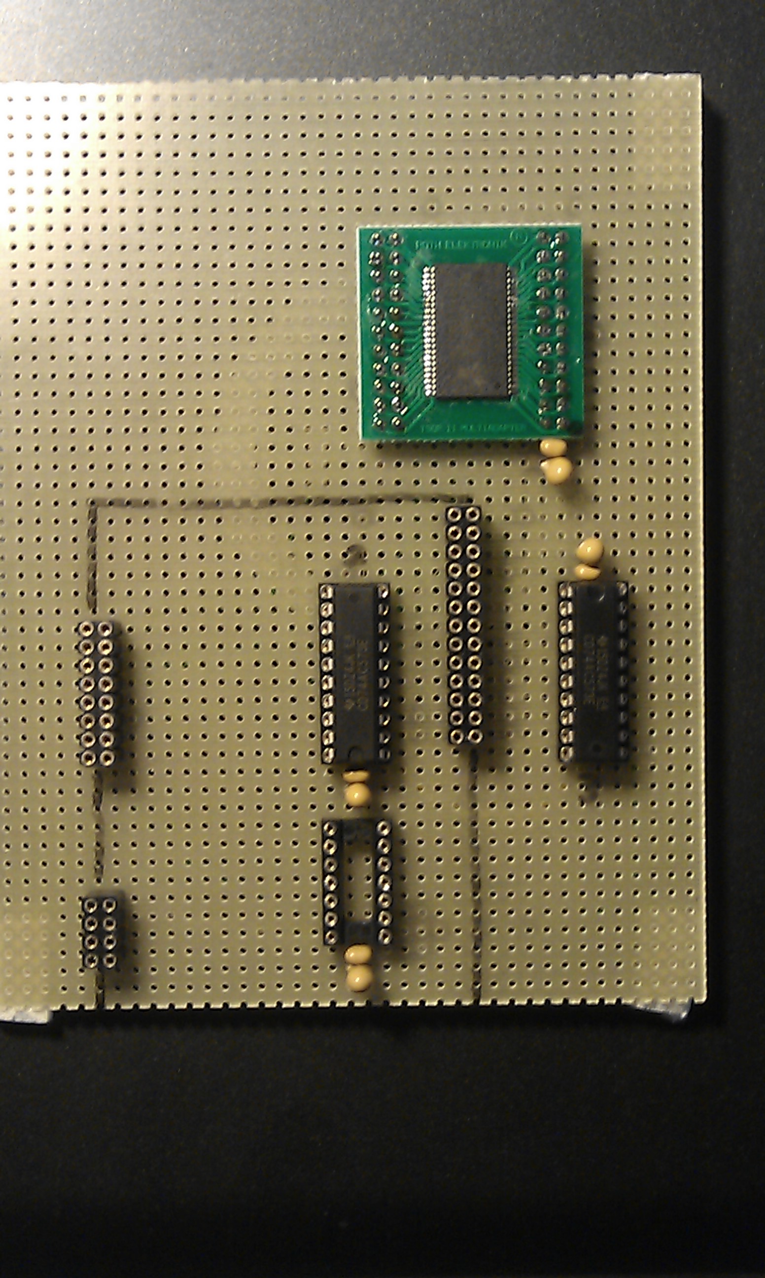
Um ein externes SRAM an das STM32F4-Discovery-Board anzuschließen, habe ich eine Lochrasterkarte als Basisboard benutzt und dort das SRAM und die Zusatzbeschaltung draufgelötet.
Wichtig !! wegen einer Doppelbelegung von Pin PD5 sollte der 0 Ohm Widerstand R50 auf dem Discovery-Board entfernt werden !!
Schaltplan :
Bild :
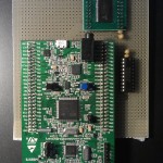
- Discovery-Board und SRAM

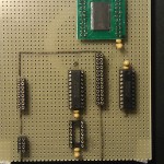
- Lochrasterkare
Beschreibung :
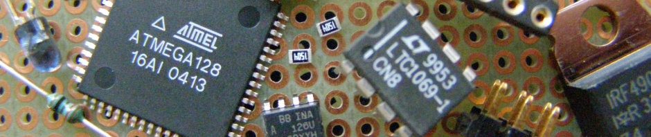
Das SRAM habe ich bei Farnell gekauft (BstNr. : 1562920) es ist ein 4Mbit [256k x 16bit] Modul mit einer Geschwindigkeit von 10ns (8,60 EUR).
Weil auf dem Discovery-Board die Adressleitungen A0 bis A15 nicht vorhanden sind (wegen dem 100Pin-Package der CPU) muss der Berieb der FSMC-Schnittstelle im Adress-Multiplex-Mode erfolgen. Dafür sind dann noch Adress-Latches notwendig (z.B. 74573). Und weil das Latch-Enable-Signal der CPU Lo-Activ ist, wird noch ein Inverter benötigt (am besten ein schneller VHC-Typ z.B. 74VHC04)
Geschwindigkeit :
Beim ersten Quick&Dirty Test komme ich beim lesen auf ca 6,0 MByte/sec und beim schreiben auf 6,8 MByte/sec.
Benutzte Pins :
1 2 3 4 5 6 7 8 9 10 11 12 | PD0 =RAM_AD2 PB7 =Latch_Enable (Lo-Aktiv) PD1 =RAM_AD3 PE7 =RAM_AD4 PD4 =RAM_OE PE8 =RAM_AD5 PD5 =RAM_WE PE9 =RAM_AD6 PD7 =RAM_CE PE10=RAM_AD7 PD8 =RAM_AD13 PE11=RAM_AD8 PD9 =RAM_AD14 PE12=RAM_AD9 PD10=RAM_AD15 PE13=RAM_AD10 PD11=RAM_A16 PE14=RAM_AD11 PD12=RAM_A17 PE15=RAM_AD12 PD14=RAM_AD0 PD15=RAM_AD1 |
Voraussetzungen :
1 2 | Benutzte Module der CooCox-IDE : GPIO, FSMC Benutzte Librarys : keine |
Funktionen :
1 2 3 | ErrorStatus UB_SRAM_Init(void); // zum init vom RAM (und Test ob vorhanden) void UB_SRAM_Write(uint32_t adr, uint16_t wert); // zum schreiben eines 16bit Wertes in das RAM uint16_t UB_SRAM_Read(uint32_t adr); // zum lesen eines 16bit Wertes aus dem RAM |
Beispiel :
1 2 3 4 5 6 7 8 9 10 11 12 13 14 15 16 17 18 19 20 21 22 23 24 25 26 27 28 29 30 31 32 33 34 35 36 37 38 39 40 41 42 43 44 45 46 47 48 49 50 51 52 53 54 55 56 57 58 59 60 | //-------------------------------------------------------------- // File : main.c // Datum : 19.07.2013 // Version : 1.0 // Autor : UB // EMail : mc-4u(@)t-online.de // Web : www.mikrocontroller-4u.de // CPU : STM32F4 // IDE : CooCox CoIDE 1.7.0 // Module : CMSIS_BOOT, M4_CMSIS_CORE // Funktion : Demo der SRAM-Library // Hinweis : Diese zwei Files muessen auf 8MHz stehen // "cmsis_boot/stm32f4xx.h" // "cmsis_boot/system_stm32f4xx.c" //-------------------------------------------------------------- #include "main.h" #include "stm32_ub_sram.h" #include "stm32_ub_led.h" void Delay(__IO uint32_t nCount) { while(nCount--) { } } int main(void) { uint32_t adr; uint16_t sollwert, istwert; ErrorStatus ramcheck; SystemInit(); // Quarz Einstellungen aktivieren // Init der Orangen LED UB_Led_Init(); // init vom externen SRAM (und test ob es vorhanden ist) ramcheck=UB_SRAM_Init(); if(ramcheck==SUCCESS) { // zum test RAM komplett füllen sollwert=0xA1B2; for(adr=0;adr<SRAM_MAX_ADR;adr++) { UB_SRAM_Write(adr,sollwert); sollwert++; } // Ram wieder auslesen und prüfen sollwert=0xA1B2; for(adr=0;adr<SRAM_MAX_ADR;adr++) { istwert=UB_SRAM_Read(adr); if(istwert!=sollwert) { // RAM-Inhalt fehlerhaft ramcheck=ERROR; } sollwert++; } } while(1) { if(ramcheck==SUCCESS) { // wenn kein Fehler -> LED leuchtet UB_Led_On(LED_ORANGE); } else { // wenn Fehler -> LED blinkt UB_Led_Toggle(LED_ORANGE); Delay(500000); } } } |
Hier die Library zum Download :
Hier der komplette CooCox-Projektordner zum Download :
23 Antworten auf 50-SRAM-Library (STM32F4)
Wie hat Dir dieser Artikel gefallen?
 (Noch keine Bewertungen)
Wie ist es denn bei Farnell, also kann man Privat bei Farnell bestellen? Eigentlich ist es ja nur für Gewerbetreibende
es gibt den “hbe-shop.de” da kann man als Privat Person alles was es bei Farnell gibt bestellen. Falls ein Bauteil nicht gelistet ist, einfach per EMail Anfragen, das funktioniert normalerweise.
Hallo,
ich lass mal ein Danke hier, für die tolle Seite.
Ich will mich demnächst auch an das Thema – externer SRAM heranwagen.
Gruß Dirk
Hallo Dirk,
dann solltest du dir aber besser ein Board mit S-Ram kaufen.
Mit der 100 PIN CPU auf dem Discovery macht es nicht wirklich Sinn.
Nehm einfach 429 Discovery, da ist S-Ram mit drauf oder besorge dir ein anderes Board mit S-Ram.
Ich habe welche von POWERMCU mit SRAM NAND Flash und NOR Flash.
Oder Red Dragon 407
einfach mal googeln.
Grüße
Jörg
Guten tag!
i can’t speak german but could i ask something in english?
My question here is: why is the PB7 NL pin connected to a hex converter(?) first [74HC04] and then only connected to the flip flop/latcher? why is this step necessary?
thanks
english is no problem when you can handle my bad syntax

the nl pin (pb7) is lo aktiv but the used adress latch (74573) needs a high aktiv signal. and i didn’t find a way to switch the polarity by software. so i used the 7404 as an inverter (the other 5 gates are unused) but it must be a very fast one because of the fast timing from the fsmc-bus. and DONT DO THIS WORK !…keep your life simple and buy a STM32F429 DISCO
haha thanks for the advice!
The problem is that currently our project is based on the stm32f407 micro-controller. I was unaware that the board used a 100 pin package and so forth did not have the full FSMC pins. The only way i see now is that i go ahead with your configuration and make it work. I will have the same setup but will be using a IS61WV102416BLL 2MB SRAM instead.
By fast you mean how fast? what is the baseline through which i can make the selection? should i just go ahead with the same inverter you used in your diagram?
I will have a look at the FSMC in the datasheet as well.
Thanks a lot!
Hey there again,
you mention that R50 has to be removed? you mean literally desolder it?
thanks
And one more question!
When you say this:
[// Note: These two files must be on 8MHz
// „Cmsis_boot / stm32f4xx.h“
// „Cmsis_boot / system_stm32f4xx.c“]
Do you mean that the whole system should be clocked at 8MHz? why is this so?
the external crystal mounted on the discovery is 8MHz
(the cpu internal clock is 168MHz) the original files from ST
“stm32f4xx.h” and “system_stm32f4xx.c” are written for a board with 25MHz crystal. The user has to change these two files to work correctly with an 8 MHz crystal. i have allready done this in all my librarys and projekts and the remark text is only a info for the user to think about.
Because PD5 is connected to an output pin from U6 (STMPS2141). And the Library uses PD5 also as output. to avoid a shortcut if both outputs drives an opposite signal you have to remove R50 from the discovery board.
Thanks, changed the values of HSE and PLL_M to 8MHz and 8 respectively.
OK, i am back again
I am using an IS61WV102416BLL 1M*16 SRAM which has extra A18 and A19 pins that need to be connected as well. What I realized was that PD13 of FSMC A18 port conflicts with the orange LED. I checked to see if other pins are free too but unfortunately they are all taken by other FSMC ports.
Now my question is, can i just not connect A18 and A19 and still make it work? Will there be an issue? I could test the system out straight, but I like to know if its technically possible in the first place
you can use both pins the leds dont care.
thanks
Hi there,
I realized that the FSMC_DataAddressMux has been Enabled, I would like to know why you did so.
and also the FSMC_MemoryType has been defined as NOR and not SRAM, would you please clarify this?
Danke
I see you multiplexed it,
got my answers thanks!
Yes, on the Disco-Board with the small CPU Package there are no Adress Signals A0 – A15 so you have to multiplex it. And the Memory Type is also a “free GPIO Pin” Problem workaround.
Ok,i gave up on the project. somehow the FSMC upper bits data output values are incorrect. the lower bits are just fine.
I went ahead and bought the stm32f429 disco board. Should have listened to you earlier haha
Hallo,
hab da eine Frage zu der FSMC-Schnittstelle.
Ich verwende einen STM32F405 mit 144 Pin und einen SRAM(IS61LV5128AL) mit 512k x 8bit. Ich kann mehrmals hintereinander Bytes in den SRAM schreiben oder aber auch lesen und schreiben von Bytes im Wechsel.
Doch nur wenn ich mehrmals hintereinander Bytes aus dem SRAM lesen will, wird mir Müll ausgelesen.
Das Problem hab ich im manuellen Betrieb, also mit Hilfe der write / read Funktion, gelöst indem ich den OE Pin wieder nach einer read Funktion auf high gesetzt habe.
Doch da ich jetzt mir eine Section im Linker Script erstellt habe und das nun automatisch funktioniert, wüsste ich nicht wie ich das beheben kann.
Hätten Sie mir da ein paar Tipps / Lösungsvorschläge?
Grüße
Manu
stimmt das Timing mit dem vom Datasheet vom RAM überein ?
Ich hab Extended Mode Enable und verwende Mode A.
Bei Mode A muss ich ja nur AST, DST und BusTurn einstellen.
Dafür hab ich dann AST, DST auf 1 und BusTurn auf 0.
Wobei ich aber sagen muss, dass ich nicht weis was mit BusTurn gemeint ist bzw. was der NEx Pin sein soll. (aus dem Daenblatt: Time between NEx high to NEx low)
bei meinem fliegenden Aufbau funktionieren so kleine Werte gar nicht. Versuch mal zuerst extrem große Werte
AST=15, DST=15, AHT=15 und prüfe ob es damit geht.