Das hier ist die Projekt-Seite vom Mini-Oszilloskop per STM32F429-Discovery-Board.
Das ganze soll mehr den Anspruch als “Schätzeisen” und nicht dem von einem “Messgerät” haben. Also nicht hoffen das man mit dem Ding hoch genaue Messungen machen kann.
Analoge Eingänge :
CH1 an PA5
CH2 an PA7
Hinweis :
An die Analog-Eingänge dürfen nur Spannungen zwischen 0V und Vref (+3V) angelegt werden !! Am besten durch eine externe Beschaltung die Pins gegen unerlaubte Spannungswerte schützen !!
Digitale Ausgänge :
UART-TX an PA9
500Hz Testsignal an PB2
Version :
V:1.6 vom 24.03.2014
implementierte Funktionen :
Analog-Kanäle : 2 (per ADC1 und ADC2)
ADC-Mode : Dual regular simultaneous mode (ADC1+2 werden gleichzeitig gemessen)
DMA-Mode : Double-Buffer-Mode (zwei Buffer die alternierend beschrieben werden)
Navigations-Steuerkreuz : per Touch (Halbtransparent)
Steuerkreuz an 3 Positionen vom Display einblendbar und abschaltbar.
Trigger-Quelle : CH1 oder CH2
Trigger-Flanke : Hi- oder Lo-Flanke
Trigger-Mode : “normal” , “auto” , “single”
Trigger-Value : 0,0V bis 3,0V
Triggerposition : fix bei Display Mitte
“Run/Stop” Button zum stoppen der Aufzeichnung (per Hardware User-Button)
Timebase : einstellbar von 5sec/div bis 25us/div (max = 1MHz Samplerate)
CH1 : einstellbar von 5V/div bis 0,1V/div (an Pin PA5 [0…3V])
CH2 : einstellbar von 5V/div bis 0,1V/div (an Pin PA7 [0…3V])
CH1+CH2 : ein/ausblendbar + Y-Position verschiebbar
Cursor : Off, CH1, CH2, Time oder FFT
FFT : von CH1 oder CH2 (abschaltbar)
ADC und FFT-Daten können per UART an einen PC gesendet werden
Der Oszi-Screen kann als BMP-File per UART zum PC gesendet werden
UART Setting : 115200 Baud / 8N1
500 Hz Testsignal (Rechteck)
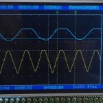
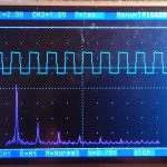
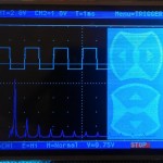
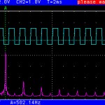
Screenshot :
- 2 Kanal Oszi mit Cursor
- mit FFT-Funktion
- mit aktivem Menu
- Oszi-Screen als BMP-File
Falls jemand einen Fehler findet oder einen Wunsch für eine Erweiterung hat, dann einfach einen Kommentar schreiben.
Hier der komplette CooCox-Projektordner zum download :


Ich dachte immer man verbringt Weihnachten mit der Familie
Sehr cooles Projekt, auch wenn ich mich gerade nicht traue, etwas ohne Sicherheitsmaßnahmen an den ADC zu hängen. Möglich und nicht zu kompliziert wäre vielleicht ein Op-Amp als Vorverstärker (evtl. in ein paar Stufen schaltbar), ein Tiefpass ein Stück über der sinnvollen Maximalfrequenz – wie ist die eigentlich, Pi * Daumen? – und eine Spannungsbegrenzung. Bin aber leider nicht so der Profi-Elektroniker; abgesehen davon fehlt mir das Messequipment, z.B. ein Oszilloskop. Mal sehen, wo man Anregungen finden kann.
ich hab im Moment auch nur eine “offene Leitung” als Antenne drann. Dann mit einem Finger drannfassen und man hat ein schönes “Brummsignal” zum messen
Hi,
hier gibt’s noch ein paar Anregungen:
http://www.youtube.com/watch?v=JQhHKdDDgM0&sns=em
Da sieht man mal was mit dem tollen Board alles möglich ist, wenn mans kann.
Schönes Projekt,danke dafür!
Jetzt muss ich mir noch ein zweites Board bestellen, damit ich auch messen kann wenn ich am basteln bin^^
Grobe Fehler habe ich bei meinem Test nicht gefunden, aber für gutes Handling ist ein “Touch-Stift” hilfreich, zumal auch das Display wackelig verklebt ist.
Die Cursorfunktion erschließet sich mir nicht so wirklich, ich habe doch die V/div Anzeige um mein Signal zu bewerten? evtl. könnte man diese Anzeige als Auto Min-Max/ Peak-Peak nutzen
Hallo und Danke,
ich habe Show_10_Oszi.zip\Show_10_Oszi\stm32f429\Debug\bin\stm32f492.hex geflasht und bekomme die Ausgabe “Touch ERR”
Das Problem gab es mit deinem PacMan Klon nicht.
den Fehler bekomme ich auch ab und zu. Steck mal USB aus und wieder an um das Board neu zu starten, dann müsste es wieder gehen.
Hallo,
danke fuer ein Beispiel zur Darstellung der DSP-Faehigkeiten des Prozessors. Aber warum sind die Compilereinstellungen fuer die FPU auf Sofwareemulation gestellt? (float-abi=soft)
sG.
du kannst es auch auf “FPU hard” umstellen…kommt auf das gleiche raus. Die Berechnung wird nur einmal pro Anzeige refresh gemacht (alle 50ms) das spielt die Geschwindigkeit keine Rolle.
klasse, danke für die FFT Funktion, das freut mich
ich bin mir nicht ganz sicher ob sie das macht was sie soll ich kenn mich mit FFT nicht so aus…muss das erstmal nochmal in Ruhe nachmessen.
(z.B. ist der erste Wert der FFT immer 100% … das kann so nicht ganz stimmen)
Der 1. Wert sollte die Amplitude (u. Phase) fuer Freuqenz = 0, also den Gleichspannungsanteil angeben.
Soweit ich gesehen habe verwendest du die FFT fuer Komplexe Zahlen, ohne dass ich mir den Source-Code angesehen habe, denke ich was du brauchst sind die ‘Real FFT Functions’ (arm_rfft_f32 – siehe CMSIS DSP Dokumentation).
Danke, hab es geändert…so sehen die Daten plausibler aus.
Tolles Projekt, sowas habe ich mir schon laenger gewuenscht!
Hier ein paar Anregungen:
Man koennte den Touchscreen mehr nutzen: Z.B. koennte man, je nachdem was im Menu-Mode ausgewaehlt ist, z.B. den Y Offset verschieben (Ch1/Ch2) oder Trigger Level und Zeit aendern, jenachdem wo auf dem Touchscreen getippt wird…
Nett waere auch ein simpler Frequenzgenerator, damit man dann gleich das Scope testen kann.
Dann noch run/stop per User Button?
Nochmals Danke fuer das schoene Programm,
Gruss,
Markus
Ja, die Bedienung ist ein echtes Problem. Muss mal schauen ob mir da was besseres einfällt. So wie es jetzt ist, war es halt am einfachsten umzusetzen.
lade dir mal Version 1.4 runter.
Da ist jetzt die Menusteuerung neu. User-Button = Run/Stop. PB2 = 500Hz Rechteck.
Super, schon viel leichter zu bedienen… Mal sehen, wenn ich etwas Zeit finde, dann entwerfe ich eine kleine Aufsteck- (oder Untersteck-) Platine mit einer passenden Vorstufe.
Dann kannst du auch gleich noch 5 Buttons (oder so ein SMD-Mini-Joystick) zur Bedienung einplanen
Das ist jetzt eine ziemlich runde Sache. Danke!
Respekt, wirklich ein gelungenes Teil.
Mit einem passenden Gehäuse und etwas vorbeschaltung auch sicherlich mal für eine Messung unterwegs tauglich. Leider bin ich nicht ganz firm mit der Programmierung von ST Controllern.
Die FFT ist auch ein Kracher, echt Klasse.
Was allerdings aus meiner Sicht noch erweiterbar wäre: 5 Tasten steuerkreuz als externe Taster beim Oszi
evtl. eine Multimeter funktion zur Frequenz und Spannungsmessung
evtl. ein einfacher DAC Ausgang mit Sinus, Rechteck, Dreieck,PWM
ich weiß nicht was RAM und Co so hergeben, aber könnte man ein paar Portpins als Logic analyzer hernehmen um die Daten dann an den PC oder USB Stick oder SD Karte zu senden?
ja, machbar ist viel, im RAM ist noch massig Platz. Einzig die Steuerung und die Samplerate ist halt schrott. Um das ganze “vernünftig” zu machen müsste man wirklich eine Platine designen, aber dafür fehlt mir das Geld und die Lust.
wäre es möglich den USB Seriell Wandler vom Funktionsgenerator zu nutzen und beide projekte zu einem zu machen?
Also nach dem Start wahlweise Funktionsgenerator oder Oszi starten?
Das wäre aus meiner Sicht sehr sinnvoll.
Tolles Projekt! Ich werde mir auch bald (nächten Monat) ein STM32F429-Disco zum spielen anschaffen.
Da ich gerade mit der Platinenherstellung daheim angefangen habe könnte ich vielleicht bei einem Erweiterungs-Board helfen.
Super Arbeit, weiter so!
Program doesn’t run when any optimisations are enabled.
In file stm32_ub_systick.h line 28 you need “volatile uint32_t GUI_Timer_ms;”
It then work as normal.
Nice little project by the way
thanks for the info
Hallo
Ich bin auf der suche nach einem Beispielcode für eine FFT von einigen ADC-Werten. Dabei bin ich auf deine Software gestossen. Ich brauche allerdings kein Display und auch die anderen Funktionen nicht.
Gehe ich richtig in der Annahme, dass dieser Code grundsätzlich auch auf einem STM32F407 Discoveryboard funktionieren sollte?
Hast du die FFT Library evt. bereits an einem anderen Ort verwendet und erläutert (vielleicht in einem etwas kleineren, daher übersichtlicherem Projekt)?
Besten Dank und liebe Grüsse
Simon
das müsste auf jedem STM32F4 laufen. Die notwendigen DSP Files liegen alle im Ordner “fft_lib” da kannst du ja neuere Versionen vom STM32F07 nehmen (aus dem DSP-Firmware-Package). Und als Beispiel kannst du dich ja am FFT.c und FFT.h vom Oszi-Projekt halten.
Da gibt es ein Eingangs-Array mit den ADC-Werte (in Float gewandelt und Nullpunktsymetrisch) und ein Ausgangs-Array in dem später die FFT liegt
// init der FFT

fft_init();
// fuellen vom Eingangs Array mit ADC-Werten
FFT_DATA_IN[0…511] = (float32_t)((adc_wert-2048.0)/1000.0);
// FFT berechnen
fft_calc();
// Ausgangswerte
uint16_t fft_wert=FFT_UINT_DATA[0…255]
kein großes Hexenwerk
Danke viel Mals für die Ausführliche Antwort.
Eine kleine Frage habe ich noch: Im header-file schreibst Du bei FF_LENGTH, don’t Change. Bezieht sich das auf deine Anwendung mit dem Display? Grundsätzlich gibt es keine Einschränkungen zur Anzahl Samples im Code, richtig?
Danke für die Hilfe
Simon
laut Doku der realFFT von ST sind nur die Längen “128,512,2048″ erlaubt.
Hello, I’m beginning to study microcontrollers, and saw your project and carried away quite, very good, I do it, however, I do not understand the mounting lcd, if you can teach me I thank.
you have: PA3 = G2 PD3 = G7
// PA4 = VSYNC PD6 = B2
// PA6 = G2 PD13 = WRX (CMD/DATA)
// PA11 = R4 PF7 = SPI_CLK
// PA12 = R5 PF8 = SPI_MISO
// PB0 = R3 PF9 = SPI_MOSI
// PB1 = R6 PF10 = DE (Enable)
// PB8 = B6 PG6 = R7
// PB9 = B7 PG7 = CLK
// PB10 = G4 PG10 = G3
// PB11 = G5 PG11 = B3
// PC2 = SPI_CS PG12 = B4
// PC6 = HSYNC
// PC7 = G6
// PC10 = R2
I have: PD14 -FSMC_D0
PD0 -FSMC_D2
PE7 -FSMC_D4
PE9 -FSMC_D6
PE11 -FSMC_D8
PE13 -FSMC_D10
PE15 -FSMC_D12
PD9 -FSMC_D14
LCD_CS – PD7
PD5 – FSMC_NWE – LCD_WR
PB0 BL_PWM
PC4 LCDTP_CS
LCDTP_DIN PB15
PD15 – FSMC_D1
PD1 – FSMC_D3
PE8 F -SMC_D5
PE10 – FSMC_D7
PE12 – FSMC_D9
PE12 – FSMC_D9
PD8 – FSMC_D13
PD10 – FSMC_D15
LCD_RS – FSMC_PD11
PD4 – FSMC_LCD_RD
PC5 – LCDTP_IRQ
PB13 – LCDTP_CLK
PB14 – LCDTP_DOUT Open407V-D
Thank You.
Rodrigo – Brazil
The used LCD on the STM32F429-Disco Board is connected to the TFT-Interface of the MCU. These Interface is not compatible with the FSMC-Interface from the STM32F407 MCU. Please have a look at the datasheets of the different MCUs.
thanks for the attention given.
Hi, ubecker
Thank you very much for your code, with your FFT example, I can make a simple Oscilloscope with stm32f103zet board. Here’s the link:
http://www.electoday.com/index.php/topic,11938.0.html
Please you see, if some points are not correct please you advice. I just start with stm32f4, do not understand your project yet. I must learn your programming pattern from beginning with stm32f4discovery’s projects.
Thanks.
Hello, Thamanoon!
I know, it is several years old now, but I would like to ask, those oscilloscope codes that are in link you provided – is there maybe some additional resource about it, maybe blog, webpage? Or, some short annotation in english maybe is possible? Thank You very much in advance!
Please tell me what this comment means
case 7 : // 20ms=>1,25kHz=800us (adc.c)
at this point the settings for the timer period and prescaler is set.
Case7 = the user has selected a horizontal resolution of 20ms/div
20ms = 50Hz per div
(one div = 25 pixel at the display)
50 Hz * 25 = 1,25 kHz per pixel
the Timer-2 is running with 84MHz
to get the right resolution you need a devider of
84MHz / 1,25kHz = 67200
i have chosen (42 * 1600) to do this
How to change the 500Hz test signal to 2500Hz ? Please help me
the systick interval is used to toggle PB2 and these interval is fix at 1ms. so you can’t change that. but you can use a free timer and generate another signal on another free gpio pin with 2,5kHz. if you need a example leave a message.
Yes please provide me an example of 2.5kHz
please provide me an example of 2.5kHz
//----------------------------------------------------------------------

// includes

//----------------------------------------------------------------------

#include "stm32f4xx_gpio.h"

#include "stm32f4xx_rcc.h"

#include "stm32f4xx_tim.h"
//———————————————————————-
void INIT_PB7_AF_TIM4(void)
{
GPIO_InitTypeDef GPIO_InitStructure;
// clock enable
RCC_AHB1PeriphClockCmd(RCC_AHB1Periph_GPIOB, ENABLE);
// set pin as AF-Function
GPIO_InitStructure.GPIO_Pin = GPIO_Pin_7;
GPIO_InitStructure.GPIO_Mode = GPIO_Mode_AF;
GPIO_InitStructure.GPIO_OType = GPIO_OType_PP;
GPIO_InitStructure.GPIO_PuPd = GPIO_PuPd_UP;
GPIO_InitStructure.GPIO_Speed = GPIO_Speed_50MHz;
GPIO_Init(GPIOB, &GPIO_InitStructure);
// connect Pin PB7 to TIM4
GPIO_PinAFConfig(GPIOB, GPIO_PinSource7, GPIO_AF_TIM4);
}
//———————————————————————-
void INIT_TIM4_CH2_2500HZ_TOGGLE(void)
{
TIM_TimeBaseInitTypeDef TIM_TimeBaseStructure;
TIM_OCInitTypeDef TIM_OCInitStructure;
// clock enable
RCC_APB1PeriphClockCmd(RCC_APB1Periph_TIM4, ENABLE);
// set period + prescaler :
// Timer-4 = 84MHz
// 84MHz/200/84 = 5000Hz
TIM_TimeBaseStructure.TIM_Period = (200-1);
TIM_TimeBaseStructure.TIM_Prescaler = (84-1);
TIM_TimeBaseStructure.TIM_ClockDivision = TIM_CKD_DIV1;
TIM_TimeBaseStructure.TIM_CounterMode = TIM_CounterMode_Up;
TIM_TimeBaseInit(TIM4, &TIM_TimeBaseStructure);
// set OutputCompare-CH2 : toggle at compare
TIM_OCInitStructure.TIM_OCMode = TIM_OCMode_Toggle;
TIM_OCInitStructure.TIM_OutputState = TIM_OutputState_Enable;
TIM_OCInitStructure.TIM_OCPolarity = TIM_OCPolarity_High;
TIM_OC2Init(TIM4, &TIM_OCInitStructure);
// Timer enable
TIM_Cmd(TIM4, ENABLE);
}
try this,
not tested but should toggle PB7 with 2500 hz
Leider kann der Assembler code in startup_stm32f4xx.c in der aktuellen CoIDE mit GNU Tools ARM Embedded\4.9 2014q4 nicht übersetzt werden:
[cc] … Temp\ccUiuOvE.s: Assembler messages:
[cc] … Temp\ccUiuOvE.s:187: Error: selected processor does not support Thumb mode `it lt’
[cc] … Temp\ccUiuOvE.s:188: Error: Thumb does not support conditional execution
[cc] … Temp\ccUiuOvE.s:193: Error: unexpected character `w’ in type specifier
[cc] … Temp\ccUiuOvE.s:193: Error: bad instruction `ldr.w R0,=0xE000ED88′
[cc] … Temp\ccUiuOvE.s:195: Error: unshifted register required — `orr R1,R1,#(0xF<<20)‘
und in Keil gibt es noch viel mehr Fehler.
Mit CooCox 1.7.7 klappt alles bestens. Super Projekt!
Hello, i want to program a STM32F4 board so it can transmit a voltage to a pin and then stop for a while and then again transmit voltage to the pin. I want to program the board so it can send periodically voltage to a ultrasound transducer. It has to do something like this:
http://upload.wikimedia.org/wikipedia/commons/thumb/9/9e/Duty_cycle_general.png/350px-Duty_cycle_general.png
Can someone help me please? I have programmed easy things like turning on the leds but i’m stuck for doing this.
Thank you very much
http://mikrocontroller.bplaced.net/wordpress/?page_id=1013 look there
Hallo,
ich habe die Oszivariante mit dem stm32f407VG “versucht” als 2Kanal Oszi.
Nach senden eines Zeichens vom Terminal sollen ADC1 und ADC2 parallel jeweils 500 Messungen machen und dann die Werte ans Terminal senden.
Messen und Senden mit nur einem Kanal funtioniert, aber sobald ich jetzt das Programm auf zwei Kanäle erweitert habe bekomme ich erst nach mehreren Messungen ein Ergebnis auf dem ersten Kanal und im zweiten Kanal nichts. Nach weiteren Messungen sind die Werte vom ersten Kanal im Register vom Zweiten.
Verzweiflung ob Terminalprogramm oder das vom MC falsch ist.
Kann ich den Code im ganzen reinstellen oder besser als ZIP oder Ähnliches?
ich suche keine Fehler in fremdem Code, sorry.
Kein Problem, habs gefunden. War im Terminalprogramm beim auslesen.
Nice project
can try make one more powerfull ,with external adc max1197
I’m new in arm , stm32f429 can put data in ram at 60Msps ?
Hallo,
ich nutze das Oszilloskop gerne, weil mir momentan nichts exakteres zur Verfügung steht. Ich fände es gut, wenn man die aktuellen Einstellungen speichern könnte, damit man nach einem Neustart nicht erst alles wiederherstellen muss.
MfG
Lars
wo sollten die daten gepspeichert werden ?
event. könnte man die SD-Karten Library einbinden,
dann müsste man aber eine SD-Karte anschließen
(ziemlicher Aufwand)
Einfacher wäre ein Parser für die Ser. Schnittstelle
dann müsste halt immer der PC daneben stehen
Hi,
wie wäre es mit dem internen Flash? Implementiert man das Speichern als Menu-Option, dann sollte der Flash auch nicht allzu sehr belastet werden.
MfG
Lars
Hallo,
sehr nettes Projekt. Ich baue es mit Em::Blocks mit HardFP und es funktioniert auch gut, solange man keine Optimierung einstellt. Sobald irgendetwas ungleich -O0 verwendet wird, friert die Anzeige ein. Als Grund konnte ich GUI_Timer_ms entlarven. Das muss mMn volatile deklariert werden. Dann läuft es hier auch mit -O2.
VG Frank
Hi,
Hast Du bei Deinem Projekt herausfinden können welchen Wertebereich die CMSIS-FFT auswirft?
Ich meine als Beispiel: Ich habe einen 16 Bit ADC, 0-65535 entspricht z.B. 0-5V, den füttere ihn mir einem reinen Sinus, also Sammelwerke von 0-65535. Wenn ich das nun durch die FFT Routine schicke, dann sehen ich einen hohen Magnitudenwert bei 1KHz. Aber finde ich den 5V Pegel dort irgendwie wieder? Hast Du da eine Idee?
Gruß Martin
musst du selbst mal ausprobieren. So weit ich mich noch erinnere, skaliere ich den größten Wert so, das er eine bestimmte länge hat. Damit ist also jede Information aus dem eigentlichen Signal verloren. das müsste man als erstes löschen und dann mal sehen wie sich die FFT verhält.
Can I use 3.3v trigger or is the extra .3v too much?
vdda is only 3.0 so i think you have no chance to meassure 3.3V but .The adc-pin is protected with an internal diode and should handle 3,3V please read the datasheet first.
this is a very good project.
right now, I want to change the adc max sample rate from 1Mhz to 2.2Mhz.
the target is 2CH@2.2MHz in the same time.
so I change the 10us timer setting from prescaler=20;period=3; to prescaler=18;period=1;.
but I do some calculation and study, also trace the code from http://tech.munts.com/MCU/Frameworks/ARM/stm32f4/libs/STM32F4xx_DSP_StdPeriph_Lib_V1.1.0/Project/STM32F4xx_StdPeriph_Examples/ADC/ADC_DualModeRegulSimu
I am very confused with the adc.c, P_ADC_InitADC() and adc.h, talking about ADC max sample rate.
could you do me a favor to tell me where is the missing part?
Thank you very much.
which “missing part” do you mean ?
Hi,
I’m trying to modify your project to convert PA5 to output a 50Hz triangular waveform with DAC2. I’d appreciate any guidance you can provide.
that doesnt work. DAC-2 is connected to PA5
but PA5 is used by Channel-1 from the Oscii.
You must change this first.
Wonderful,
I was away from the office, and in need of an oscilloscope for a power analysis. You definitely saved my day.
I added lower vertical unit up to 0.001v, and changed a bit the code to support it. Where can I share my hacks ?
Thanks again for the really good work !
Hallo,
das Oszi ist echt genial. Vielen Dank für die tolle Arbeit!
Planst du auch eine Portierung auf das STM32F746-Disco Board mit dem größeren LCD? Wäre klasse.
Gruß
Michael
die idee ist gut aber ich komme im Moment zu gar nichts mehr
die idee ist fantastisch dieses starterkit (stm32f746) hat viel mehr möglichkeiten
Hello,
could it be possible to add 2 more channels?
the board still have 2 more adc inputs, PC3 ADC1 DMA channel 0 or 4
and PF6 @ ADC3 DMA channel 0 or 1.
I know that there are only 3 ADC’s and multiple channels
that each one ADC’s share the same sample and hold circuit internally
that could lead to inacurate measurements.
Thanks in advance!
in this project i used the ADC in “DUAL_MODE” so both channels
are sampled at the same time. The F4 can’t sample all 3 channels
at the same time. If you want more as two channels you have
to sample them one after another. In result you have a time delay
between these samples. But if you can live with this “failure” … go for it.
It will be difficult to implement this in my projekt,
its easier for you to start a new one.
Hello again!!
I’ve made a new project.
It’s missing many things like triggering,
user interface and many more.
But for now i can see signals OK on 4 channels on the screen.
But i’m having problem with the drawing of the signal.
Each time new drawing begins, i dont delete the previous one
and the new signal goes on the old signal, and you cant see anything after less than a second.
Could you give me a tip on how to deal with screen update please?
Thanks in advance.
I forgot the link to source.
https://github.com/papadkostas/STM32F429_4CH_SCOPE/blob/master/main.c
sorry, your code…your problem
Sag mal,
hast Du das allein programmiert? Dürfte ja ewig gedauert haben, die ganzen Grafik Effekte aus rudimentären Funktionen zusammen zu bauen usw.
Irre…
Christian
welche “Grafik-Effekte” das Menu besteht nur aus Text. Und die Buttons sind ein Bild.
who is author(s) of this project?
thats made by me.
Hallo,
tolles Projekt und für einfache Sachen super zu gebrauchen.
Aber warum startet die Software nur, wenn per USB am PC angeschlossen?
Nur mit Spannung versorgt (per USB-Ladegerät) wird der Bildschirm weiß und das war es?
Es wäre toll, wenn das auch so funktionieren würde. Wenn man nämlich an einem anderen Board arbeitet muss man zum Flashen das 429-Oszi immer abstecken.
Grüße
Sven
wieviel Strom liefert dein Ladegerät ?
Prüf mal die Spannung an der Platine wahrscheinlich geht die in die Knie.
Hallo und danke für die Antwort,
nachmessen geht gerade nicht, da ich unterwegs bin.
Ich hatte es an einem Samsung-Galaxy Lader mit 2A (sofern er die auch ohne spezielle Tricks abgibt!?) und an einem USB-3.0-Hub, der eine separate 2A-Ladebuchse ohne USB-Funktion hat.
Was lustig ist: Wenn ich erst normal per USB mit dem PC verbinde (z.B. auch über den Hub) startet die Oszi-Software normal. Wenn ich dann über die entsprechenden Pins auf dem Board zusätzliche 5V drauf bringe (von der Nur-Lade-Buchse vom Hub) und dann den “normalen” USB abstecke läuft es weiter!
Daher hatte ich auch eher auf ein Softwarethema (fehlende Startbedingung o.ä.) getippt.
komisch…softwareseitig gibt es da keine verknüpfung
schon mal den Reset Button probiert ob das hilft
sonst hab ich da auch keine Idee
ich benutze immer den PC als Quelle
p.s. ich arbeite gerade am F746 Oszi
falls du wünsche oder Ideen hast …
Hi sir i curious about how u did the pop-up “up down left right” menu after touch the screen. Which line is those code?
Hallo, Vielen Dank dafür! Und auch für die anderen Projekte die du mit der Community geteilt hast.
ich habe jetzt mein F429-DISCO Board erhalten und sofort dein Oszilloskop Software aufgespielt. Sie war für mich der Hauptgrund das Board zu bestellen!
http://bildites.lv/a/7npmye3q#ytm6u5ku
P.S.: my friend translated this in german, my german is not so good, I prefer english
… and, Merry Christmas! To Author, to Everyone!
Hey,
did you ever tried to “measure” the frequency of another STM32F4 by your project? If not, how would u connect them?
Oh, ganz übersehen, ich könnte ja auch auf Deutsch fragen
Ich habe hier ein billigen CJMCU-Board und das STM32F429ZI-DISCO. Über das Disco könnte ich anhand Deines Porjektes den kleinen “bemessen”. Aber wie würdest Du die Lösung dafür angehen?
einfach GND von beiden Platinen verbinden
und dann das Ausgangssignal mit dem Eingangspin verbinden.